Question
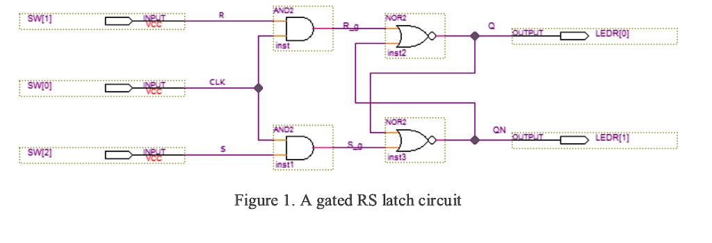
            Analyze the cross-coupled NOR gates of the Gated RS Latch in Figure 1 with inputs R_g and S_g and outputs Q and QN. Construct a truth table with inputs R_g(t), S_g(t) and Q(t) and outputs Q(t+∆t) and QN(t+∆t), where ∆t is the time required for a change of state to occur. Ignore the case when S_g(t) = R_g(t) = 1.

R
AND2
"SW[i]"
Q
OUTPUT
LEDRIO
SW[0]
CLK
QN OUTPUT
LEDR[1]
"SW[2]"
S

Figure 1. A gated RS latch circuit
Analyze the cross-coupled NOR gates of the Gated RS Latch in Figure 1 with inputs R_g and S_g and outputs Q and QN. Construct a truth table with inputs R_g(t), S_g(t) and Q(t) and outputs Q(t+∆t) and QN(t+∆t), where ∆t is the time required for a change of state to occur. Ignore the case when S_g(t) = R_g(t) = 1.
R
AND2
"SW[i]"
Q
OUTPUT
LEDRIO
SW[0]
CLK
QN OUTPUT
LEDR[1]
"SW[2]"
S
Figure 1. A gated RS latch circuit
Show more…
Added by Keith G.
Instant Answer
Step 1
The cross-coupled NOR gates in the Gated RS Latch are used to store and maintain the state of the latch. The inputs R_g and S_g control the state of the latch, while the outputs Q and QN represent the stored state. Show more…
Show all steps


Satish Kumar and 66 other
Physics 102 Electricity and Magnetism educators are ready to help you.
Ask a new question

